Sunday, November 24, 2013

MY FAVOURITE PHOTOGRAPHY PAGE

Hi.. Folks.!!

I am here with an interesting photography page. Have a look..!! Photography of this guy is awesome. Apart from electronics this time here is some intersting stuff for you all . I hope you all will enjoy it.

LINK FOR THE PAGE IS ASEEM SRIVASTAVA PHOTOGRAPHY......:)


Thanks..!!

Wednesday, October 16, 2013

MY RESISTOR CODE CALCULATOR DESKTOP APPLICATION

Hi folks!

After a long period of time I am again here . This time i have some cool stuff for electronics beginner. Here is a simple desktop application which i designed last night. By the use of this application you can easily get the value of your resistance , simply by choosing band color.

This is the link to download   My_rescode.exe.

Just download. I hope iy will help you.

For any query ,doubt or suggestion just leave a comment.

Thanks.. :)  

Sunday, April 21, 2013

HOW TO MAKE A WIRED REMOTE CONTROL ROBOT


Hi….. friends..!!   after a long time I am again here with some useful stuff . This time I am posting this article - HOW TO MAKE A WIRED REMOTE CONTROL ROBOT  to help those students who are new in field of robotics and are going to make their first robot. So if you u don’t know anything about robots don’t worry this article is going to help you guys a lot  . Just   follow this article and start your journey with robotics.

COMPONENTS REQUIRED

In order to make your first wired remote control robot you have to arrange following things-

1 robot body

4x 100rpm motor

4x robot wheels

6x DPDT switches

1 12V DC adapter OR 12v Regulated power supply ( to make your own regulated power supply you can follow this link    BASIC ELECTRONICS PROJECT 5- MAKING YOUR OWN REGULATED POWER SUPPLY  but this supply is for 5v so u just have to use IC7812 instead of 7805 for 12v supply. Or simply you can use a 12v DC adapter easily available in market)

1 soldering iron

Soldering wire and flux

10 meter BUS wire

1 vero board

                     If you want to design a PICKING MECHANISM for robotic hand you will need some more things-

2x 10 rpm high torque motors

4x spur gear

4x worm gear

Plywood and aluminum sheet

Screws

1 drill machine

Some adhesive  

Tools like screw driver hammer hack saw...etc.


LET'S START

So our most basic required is to make a power supply for robot . if you want to make your supply you can follow my article  BASIC ELECTRONICS PROJECT 5- MAKING YOUR OWN REGULATED POWER SUPPLY      but this is for making 5v volt supply so don’t worry just use IC 7812 in place of  7805 and rest of the circuit will remain same . but making your supply is somehow a tough task so I will suggest you to buy a 12V DC adapter and it will work fine .

MAKING our REMOTE

Now its time to design our controlling remote . So before designing remote you must have knowledge about connections of DPDT switch . we are using DPDT switch here because with the help of this switch we can simply drive our motor in both directions . Your DPDT switch will look something like this-


Here you can see there are 6 different pins now you have to connect motor and power supply to your switch so just pick up your soldering iron and  design this simple circuit on vero board , at first we are just going to make a remote which can control motion of robot in forward , backward , left and right direction for handwewill add some more switches but at first we are just going to use 2 switches for driving 4 motors ,

connection diagram –


     Some of you guys will be having a problem  that the DPDT switch which you have bought is having 8 pins instead of 6 and backside of that switch is looking something like this ,


 so don’t worry about connection here is connection diagram for you-


Now your controlling remote is ready for action . My remote looks like this-


So connect your motor and supply and its ready……..HOW?? ok let me show you , you are having a robot body like this –


And motors looking like this-


 Attach your motor to body as shown here-


Attach your wheels to motor-


Now connect motor terminals with the wires for motor in the remote section and connect 12Vdc to power supply terminal of robot. As shown here-


HOW TO DRIVE YOUR BOT-

We are almost done . its time to learn how to drive our bot according to our diagram we are using one switch to drive 2 motor  so-

WHEN BOTH SWITCHES ARE “UP”( pushed in forward direction)
All the motor will rotate in forward direction and robot will move forward.

WHEN ONLY RIGHT SIDE SWITCH IS UP
Only right side motors will rotate and robot will move left side.

WHEN ONLY LEFT SIDE SWITCH    IS UP
Only left side motors will rotate and bot will move turn right side

WHEN BOTH SWITCHES ARE DOWN(pushed in backward direction)
All the motors will rotate in backward direction and bot will move backward.

WHEN LEFT SWITCH IS UP AND RIGHT SWITCH IS DOWN
Robot will axially rotate right side.

WHEN RIGHT SWITCH IS UP AND LEFT SWITCH IS DOWN
Robot will axially rotate left side


 Now your robot is ready for moving but you may have some problem if you have not given proper attention , these problems may be-

1.      Motors are not rotating.
In such case check your power supply , and all the connection there may be some fault, or your motor may be faulty.

2.      While pressing a switch forward motors are rotating backward  

 You have connected opposite connection of motor to switch just change the terminals and problem will be solved

3.      While using same switch one motor is forward and one is backward
Simply connection of backward rotating motor is opposite change them.

 These are some common problem , if you are facing any other problem just let me know I’ll  give you proper solution.

 So folks..!! these are some basics of robotics in next tutorial I will post some picking mechanisms , till then GOOD BYE.......!!    stay tuned…….:)

Thursday, February 21, 2013

INTRODUCTION TO BASIC ELECTRONICS MODULE-1 EBOOK


Hi.....friends.!!

Sorry for no posting  for a long period of time but meanwhile i was busy in preparing a ebook on basic electronic components for you all. here is the first module of this ebook and i have provided some good stuff about basic electronic components.

I hope it will be of great use for you , specially for the new bees.

You can download INTRODUCTION TO BASIC ELECTRONICS MODULE-1 EBOOK here.

I am waiting for your precious views and comments.

THNX...:)


Monday, February 18, 2013

ARDUINO PROJECT 1- BLINKING LED


Hi…friends ,……welcome to ARDUINO section of my blog. In this section I am going to discuss various ARDUINO projects. ARDUINO has proved itself as a amazing platform for electronics lovers. So without wasting any time we are moving towards our first projects, obviously a “Hello world” project, in which we will blink an LED.

I am assuming you are having an ARDUINO and required software installed.( in case you are a new bee , don’t worry just let me know I will help you..:))

REQUIREMENTS

Your ARDUINO board
1 LED


CIRCUIT DIAGRAM

Circuit connections are very easy and you have to just connect led at digital pin 13 of ARDUINO as shown , connects anode of LED to digital pin 13 and cathode to ground.( ARDUINO already has 1K resistor to added to pin 13, what allows the immediate connection of a LED between that pin and ground)

LED Blinking Project Schematic


CODE

Here is the source code more commonly known as SKETCH of the project. Just upload this code to your ARDUINO and enjoy your first ARDUINO project.

/* Blinking LED
* ------------
*
* turns on and off a light emitting diode(LED) connected to a digital
* pin, in intervals of 2 seconds. Ideally we use pin 13 on the Arduino
* board because it has a resistor attached to it, needing only an LED
*/
int ledPin = 13; // LED connected to digital pin 13
void setup()
{
pinMode(ledPin, OUTPUT); // sets the digital pin as output
}
void loop()
{
digitalWrite(ledPin, HIGH); // sets the LED on
delay(1000); // waits for a second
digitalWrite(ledPin, LOW); // sets the LED off
delay(1000); // waits for a second
}


So it was just a start in our upcoming articles we will post more interesting and complex ARDUINO projects so stay tuned.

In case of any query, doubt or critical view just leave a comment.

THNX….:)

Tuesday, February 12, 2013

BASIC ELECTRONICS PROJECT 8- IMPLEMENTATION OF LOGIC GATES USING TRANSISTORS.


Hi….folks .. welcome back..!!  I am again here with another basic electronics projects for electronics beginners , this time we are going to discuss , how we can implement circuits for logic gates (AND, OR , NOT. NAND, NOR)  using transistor. With the help of these simple circuits we can easily understand the working of LOGIC GATES.

REQUIREMENTS

TRANSISTORS (BC 547)
FEW RESISTORS (220Ω)
FEW LEDs
POWER SUPPLY (5V)

CIRCUIT DIAGRAMS


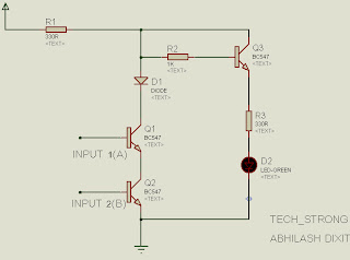
AND GATE:
Here is the simple circuit diagram for implementing AND GATE using transistors, So just implement this circuit on bread board and check the output

SYMBOL AN TRUTH TABLE                                                     CIRCUIT


HOW TO USE

You can see there are two input terminal in AND GATE and , from the truth table of AND GATE you can see the output of and gate is high only in case, when both the inputs are high, so when you will put both the inputs high LED will glow means output is high. In rest of the cases LED does not glow, means  output is low.


OR GATE

Here is the simple circuit diagram for implementing OR GATE using transistors, So just implement this circuit on bread board and check the output

SYMBOL AN TRUTH TABLE                                                     CIRCUIT


HOW TO USE

You can see there are two input terminal in OR GATE and , from the truth table of OR GATE you can see the output is low only in case, when both the inputs are low, so when you will put both the inputs low LED will not glow means output is low. In rest of the cases LED  glows, which means  output is high.

NOT GATE

Here is the simple circuit diagram for implementing NOT GATE using transistors, So just implement this circuit on bread board and check the output.

SYMBOL AN TRUTH TABLE                                                     CIRCUIT


HOW TO USE

You can see there is only one input in NOT GATE. From truth table you can see , when input is high output is low and when input is low output is high. You can check both the conditions easily.

NAND GATE

Here is the simple circuit diagram for implementing NAND GATE using transistors, So just implement this circuit on bread board and check the output.

SYMBOL AN TRUTH TABLE                                                     CIRCUIT


NOR GATE

Here is the simple circuit diagram for implementing NOR GATE using transistors, So just implement this circuit on bread board and check the output.

SYMBOL AN TRUTH TABLE                                                     CIRCUIT


NOTE : for main circuit and inputs use same power supply ........:p


I hope this article was useful for you guys , in case of any doubt, query or critical view just leave a comment.

THNX..:

Friday, February 08, 2013

BASIC ELECTRONICS PROJECT 7- WATER LEVEL INDICATOR


Hi..friends…welcome back..!! I am again here with another basic electronics project ,this time we are going to make a simple water tank overflow indicator, this is a simple project based on 555 timer IC. This project can be used as an alarm to warn us in case of overflow. Let us see how things are going on…..!!


COMPONENTS REQUIRED

NE555 IC
RESISTORS ( 1X 100K, 1X1K)
CAPACITOR (2.2uf)
1 BUZZER
POWER SUPPLY (5V)

CIRCUIT DIAGRAM

In this circuit 555 IC is used in astable mode . here is the complete circuit diagram for the setup-

Implement this circuit on a general purpose PCB then attach wire ends to the wall of tank , at a desired level , whenever water level overflows this point circuit gets completed and buzzer is activated.

I hope you guys find this article helpful , in case of any query,doubt or critical view just leave a comment.

THNX...:)